EDIT: This guide was from the beginning written as a combination of a review and a help to others. The kit has been updated since. If there are things that are incorrect now or there are other details you would want to add please do reach out. I’m on both the Voron and Formbot Discord.
EDIT2: This guide is deprecated. Please see and help out in the github-project instead. It’s been improved by alot since this was written.
I had so many issues with my old small 3D printer I decided it was time to upgrade. I spent more time on fixing issues then printing and it got frustrating really fast so here we are. I bought a Formbot kit in the end of January. It has been sitting in it’s box for a bit more then a month but a few weeks ago was finally that week. This post will be a list of issues I found with the build, where the instructions simply were wrong or where I found it to be hard to follow. But to put this into perspective this build has for the most part been a lot of fun and of several hundred pages of documentations there are a few places where things got unclear. The Voron team both surprise me of how well put together this is and inspire me. Vivedino (the company behind the Formbot kit) has put together an amazing kit, I just wish they spent a few hours on the documentation.
Thanks to
First things first. Credit where credit is due. This build would not have gone as well as it did if it wasn’t for the amazing helt of people on the Voron, Formbot and Mellow 3D Discord (do note most problems I could solve by just searching in the discord channels, please try this first). Here’s a list of people I would like to thank:
Formbot Discord:
- cashmoney
- Browzzrr V2.6568
- unkown
- ĴînRΦђ V2⁶²⁵⁷ | M⁰⁸¹
- Everest V2.6256 VT V0 ERCF
- Zv0n
Voron Discord:
- Troglomike
- rec
- ZeroBrain | V0 VT
- Hagbard V2.1070
- MemorableC V2.1002
Mellow 3D Discord:
- jay_s_uk - teamgloomy
I also watched a bunch of youtubers, for inspiration before buying and also to help me understand where things were a tiny bit unclear. As I don’t have a complete list I won’t include it but Voron-youtube, thanks!
Last but not least course a huge thanks to the Voron team!
EDIT, after publishing I’ve gotten some feedback, typos, things I’ve missed, better explainations and so on. Here’s a list of people who helped out:
Formbot Discord:
- Beluguita
Voron Discord:
- Joel V2.4771 V2.6459
- ganster_uk V2.5588
For anyone considering this build
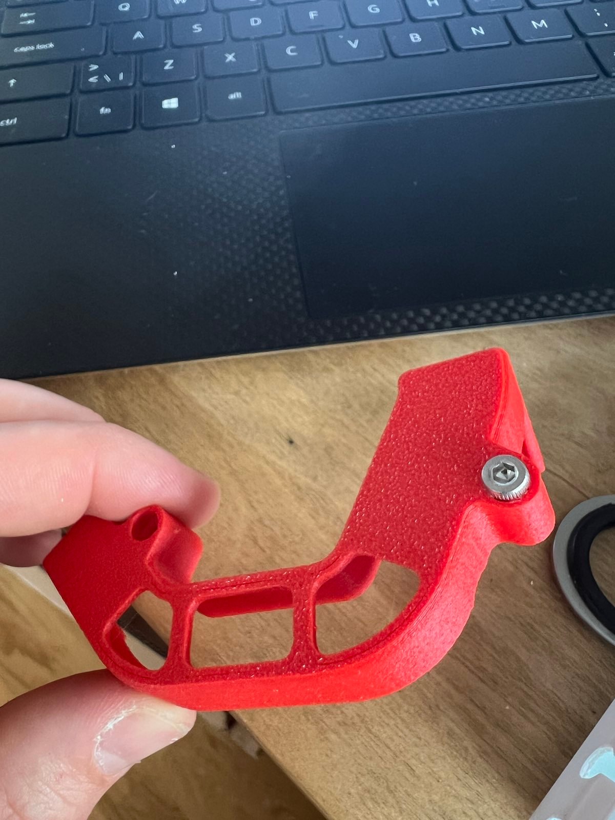
I used a long list of tools to get this kit together. If you’re not a DIY person with a pasion think twice before entering this journey. There’s no complete bill of tools needed. Mostly because it varies what you need. For instance I needed drillbits to fix a few holes a fraction to small (see image below). If you self source everything you will need a JST-crimping tool. There is a tools tab on the sourcing guide but it’s not complete. What you will need no matter what is a nice set of ball head hex key, trust me, you will use this so much is worth getting.
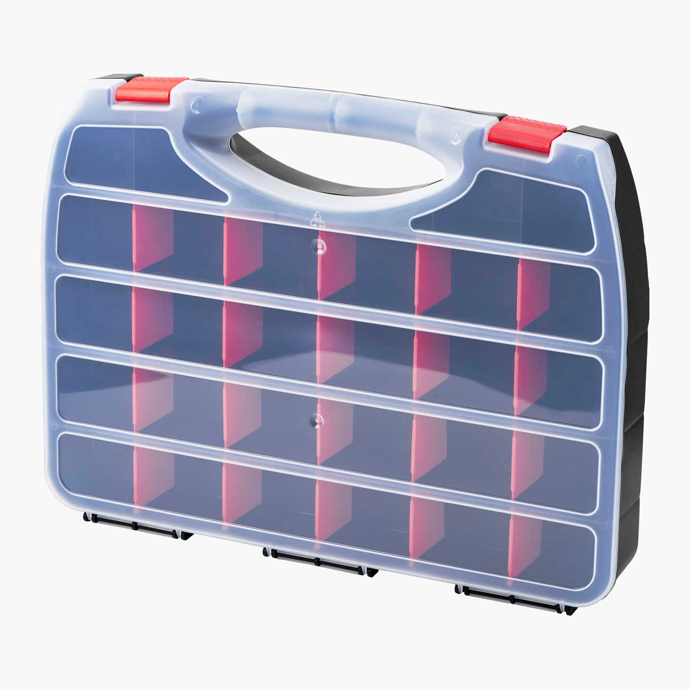
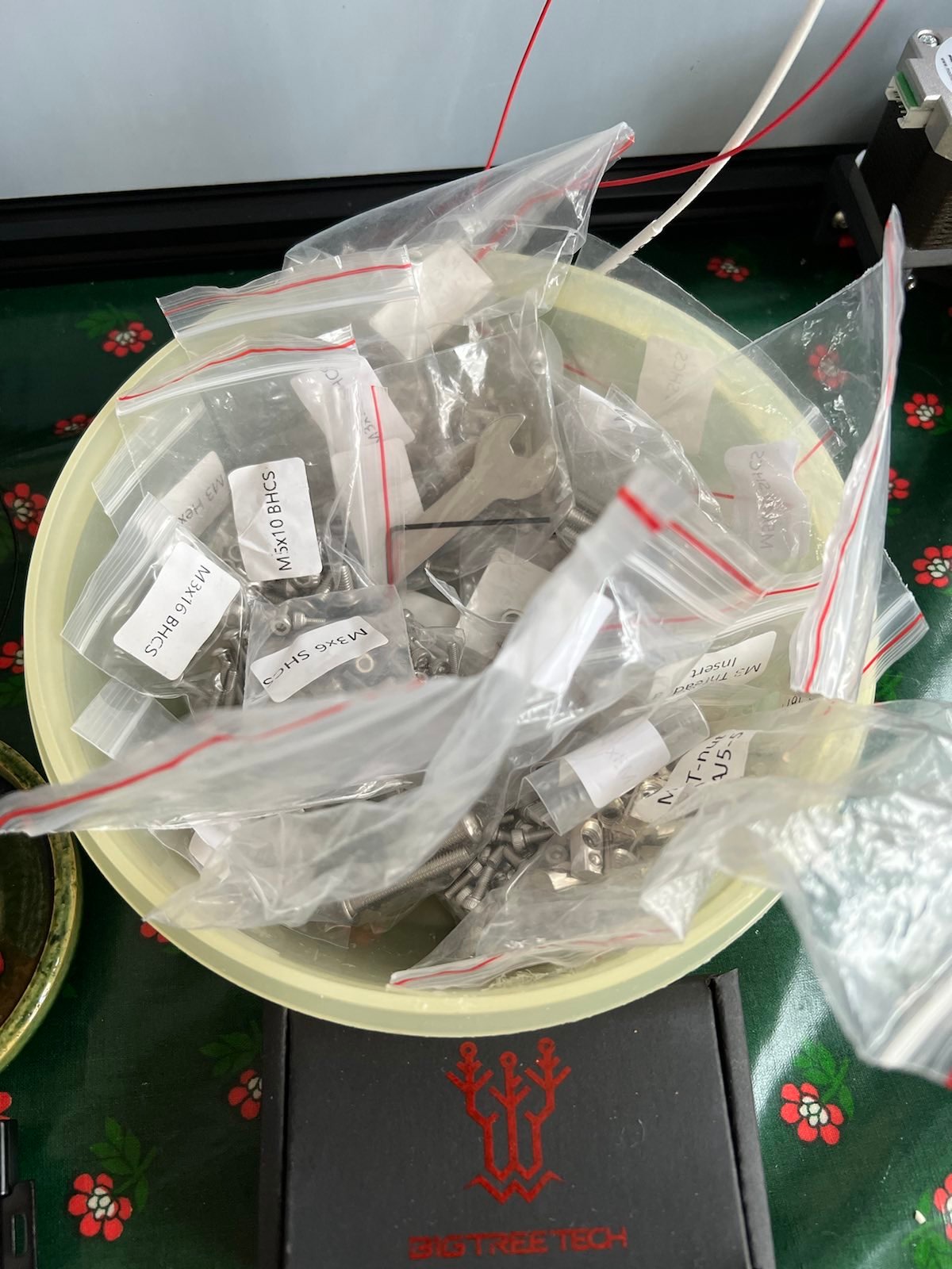
If (when) I’m to do this again, I will also spend a few bucks on some plastic sorters. Dealing with screws in ziplock-bags got old very quickly. Anything will do but I would probably buy something along the one below. If they have loose compartments use some hotglue to save yourself from dealing with walls getting loose.
Lastly, electricity, especially mains power and AC is dangerous. Please be careful.
Jumping between different PDF:s
It’s a bit hard to know where to jump when, there are at least four different PDF:s you will need, plus an image of your controller board with all pins listed (this is linked on the Voron guide on page 178). The PDF’s are:
- The Voron 2.4R2 Assembly Manual
- The Stealthburner Assembly Manual
- The Voron Tap Assembly Manual
- The Formbot wiering guide
I’ll try summerising the jumps here:
| Switch to manual | Page | Stop at page | Comment |
|---|---|---|---|
| Voron 2.4R2 | 1 | 27 | |
| 28 | Be sure to remove all protective plastic film from the deck plate, this will be difficult to remove later and might be a firehassard as well as a source to bad smell, I’ve missed this and will thus have to remove all electronics (again) and two of the motors. The deck plate should be black on one side, this is what you see with white plastic with writing on in all images below (mounted down towards the electronics). EDIT: this is now fixed, see later blogpost. | ||
| 29 | - | ||
| 30 | - | turn the DIN-rails 90 degres (if Formbot, we’ll get to why later) then continue. This does not apply to the 250, if you do this the PSU won’t fit. Will update with images when and if I get them from some kind community member | |
| 31 | 38 | ||
| 39 | - | if you build a 300x300 Formbot turn one of the motors 90 degrese so that the cable is on the same side as the two screws of the bracket, this will be Z1 later | |
| 40 | 129 | ||
| Voron TAP | 1 | 29 | The version of tap is slightly different see below. |
| Voron 2.4R2 | 131 | 142 | |
| Voron TAP | 31 | 36 | |
| Stealthburner PDF | 1 | 58 | note cabeling will be different, for this check the Formbot wiering PDF, also note there are two different dimentions of PTFE tube included, choose the correct one. |
| Voron 2.4R2 | 148 | 155 | Don’t mount anything. Also note there’s no 5V PSU but instead a extra PCB |
| 156 | Dont forget to change the fuse, it’s shipped with a 10A fuse. It should be changed for a 4A for 230V and 8A for 110V | ||
| 157 | |||
| 162 | 167 | Skip page 158-161 | |
| 175 | 177 | Skip page 168-174 | |
| Formbot Wiering guide | 1 | 4 | mount the components as shown on the image, note that is the 350x350 so if you build a smaller printer it will be tighter. There’s a picture further down in this blog-post with what is what. |
| Voron V2.4R2 | 180 | 193 | this won’t be 100% correct as there’s no 5V PSU and there’s an extra PCB, be carefull here. |
| 194 | 199 | mount cables in chains before mounting chains as it will be hard to do otherwise. Also don’t forgett the extra LED cable which is separat from the other cable (if your kit is newer then mine it’s sold with CAN-bus and this will be totally different as you probably won’t have cable chains at all) | |
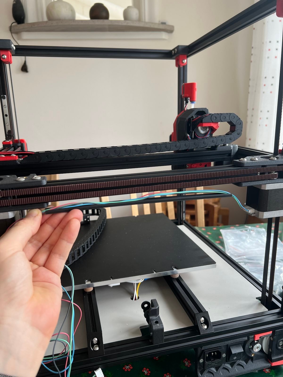
| 200 | The B-motor cable is routed in the grove under the gantry with a plastic strip instead of zipties, see image under notes below | ||
| 201 | 204 | ||
| Voron V2.4R2 & Formbot wiering PDF | Attach cables between breakout board and controll board. When you have attached the last few cables you are mostly done with what you can do now, don’t forgett to download and install the Big tree tech PI version and from it flash the octopus board via the other smaller included SD-card. | ||
| Software Configuration | Now follow the post build instructions to make sure you’ve done everything correct |
Notes from the build
The printed parts kit from Formbot
-
As my old printer had acted up I decided to buy a kit of parts from Formbot (instead of using the print it forward program). This kit was mostly fine but there are three templates used when mounting the rails on the extrusion. I’m guessing most people who buy this kit of printed parts don’t have a working printer at the moment. It would be nice if these were included. I guess some would have a printer that could print these in PLA but still. It’s three very small parts to include I would happily pay an extra few bucks for. They are avalible in in the Voron STL’s as MGN12_rail_guide_x2.stl, MGN9_rail_guide_x2.stl and pulley_jig.stl.
-
A quick note about that kit, it also would be nice if they linked what filament they used so that one could print new matching parts when done.
-
One of these printed parts was I bit to tight. The part holds the gantry together. One of the A-B belt weels got too pinched. This happens, the tolarances are very fine. I shimed the part with two layers of craft paper and it now works perfectly.
-
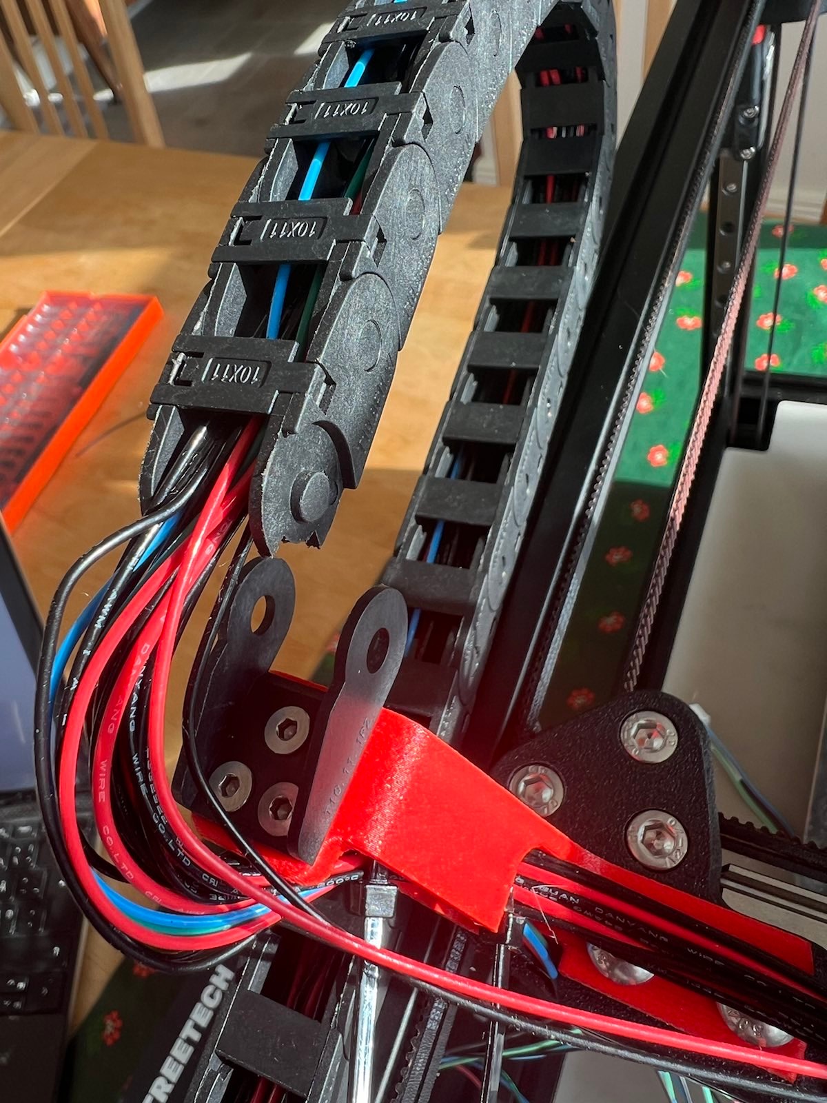
The bracket for the cables between the smaller cable chains shown on page 204 of the Voron 2.4R2 PDF was a bit to tight (see image above), I used a drillbit and just removed some plastic by hand. It’s also hard to cram all cables and a cable sleeve into, if I did not plan on modding the printer with a canbus I would probalby redesign this.
-
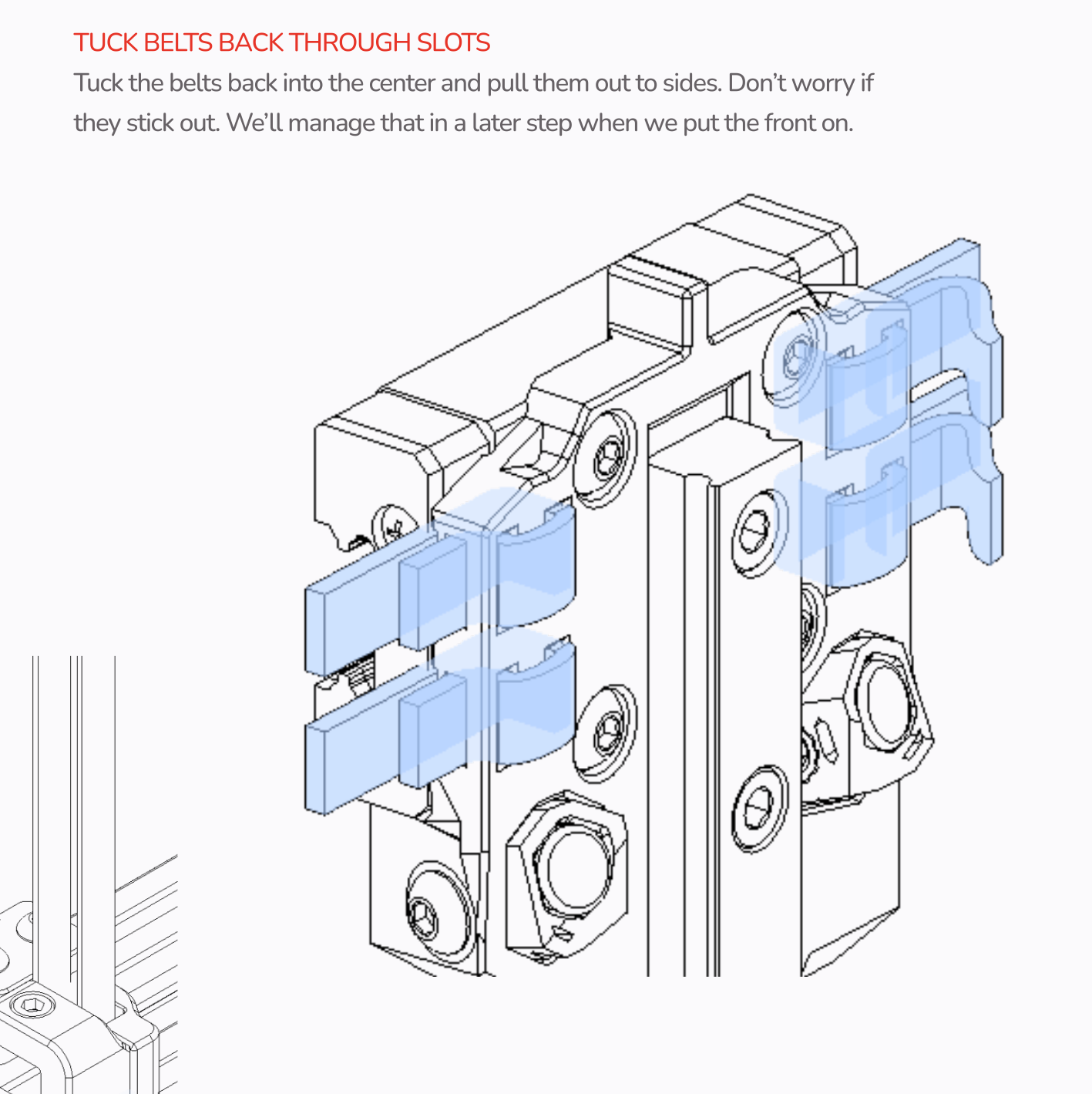
The Voron Tap plate is different from the Voron documentation, this is the R8 version. See differances in image below.
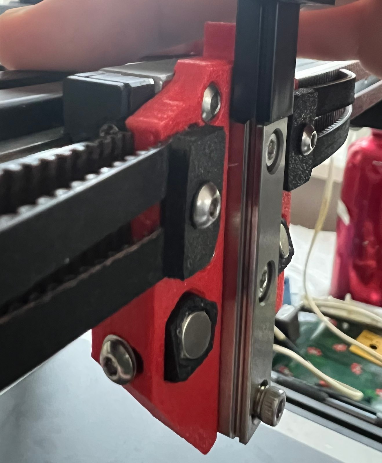 Original tap design:
-
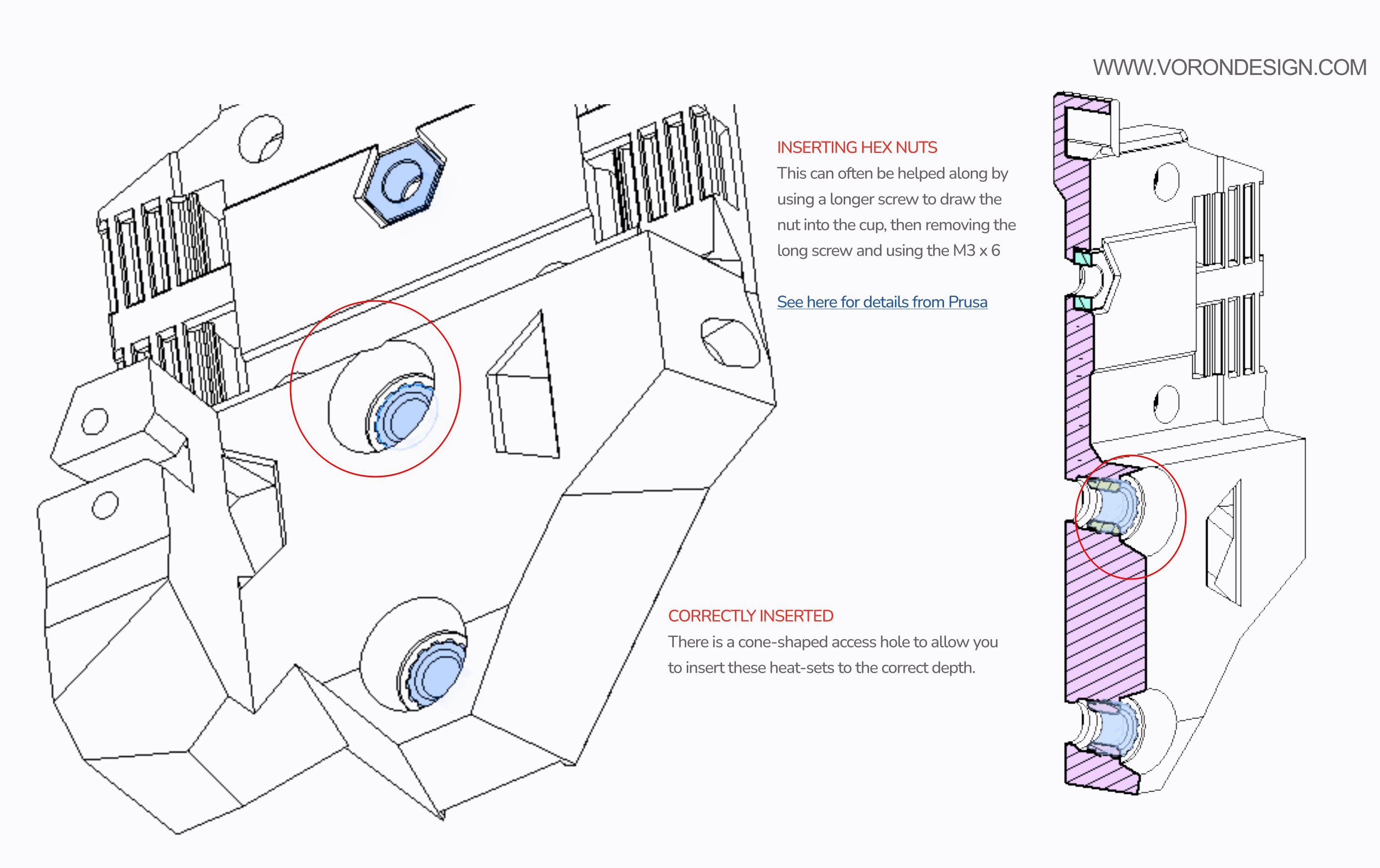
The tap plate also did not have the cone guiding you to the correct depth of the heatset incerts. Not sure why this has been changed.
 How the original STL looks:
-
The arm to cables mounted on the back of the Clockwork 2 is the wrong color. Not a big deal, just be aware when looking for it.
-
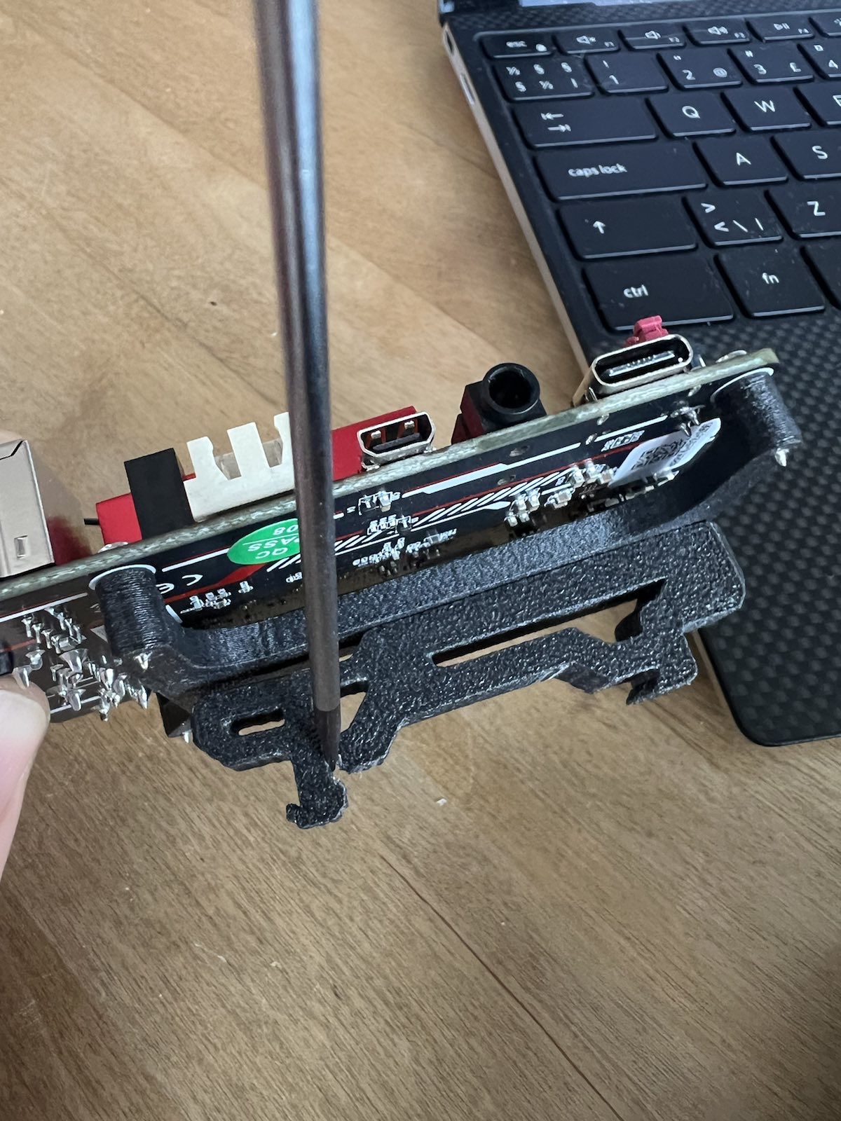
Bending the mounts with a screwdriver helped with negitioating them to bend the way they need to.
Positives with the Formbot kit
-
The driver assembly shown on page 21 of the Stealthburner PDF came pre assembled which is nice.
-
The neopixels on page 46 of the Stealthburner PDF came pre-soldered which was nice.
-
Extra screws, huge plus.
Larger issues
-
The mounting of the DIN rails are different in the Voron setup. This was by far the most anoying thing in the whole build. I of course did not notice this before trying to mounting the A and B motor cables. I had then spent some time tidying thing up. Had to redo everything. Also one of the motors has to be turned for the PSU to fit. I have no idea why they choce to do it this way nor why the documentations is so poor. It just seems odd to not make this very clear and spend some time making sure the electrical configuration guide is very clear. In frustration I asked about this on the Discord but mostly got a “everyone knows the documentation from Formbot sucks”. I hope the new kits will force an update.
-
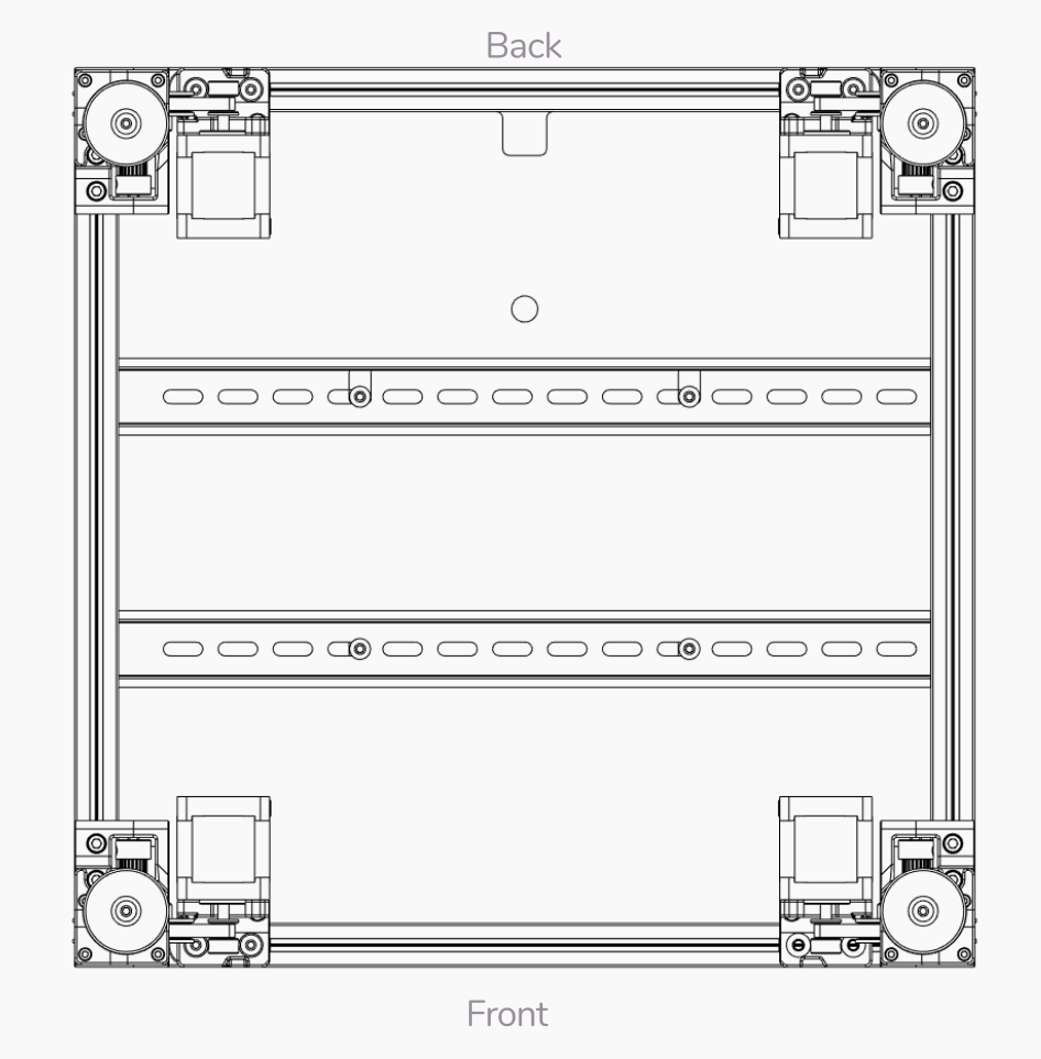
This is what the Voron guide says on page, note where front and back is.
-
This is the first page of the Formbot wiring, this is where your supposed to see that you’ve mounted the DIN-rails wrong some 100 page earlier.
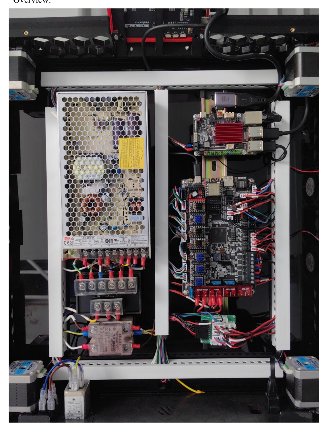
-
This lead to everything needing remounting, you could probably smell the frustration
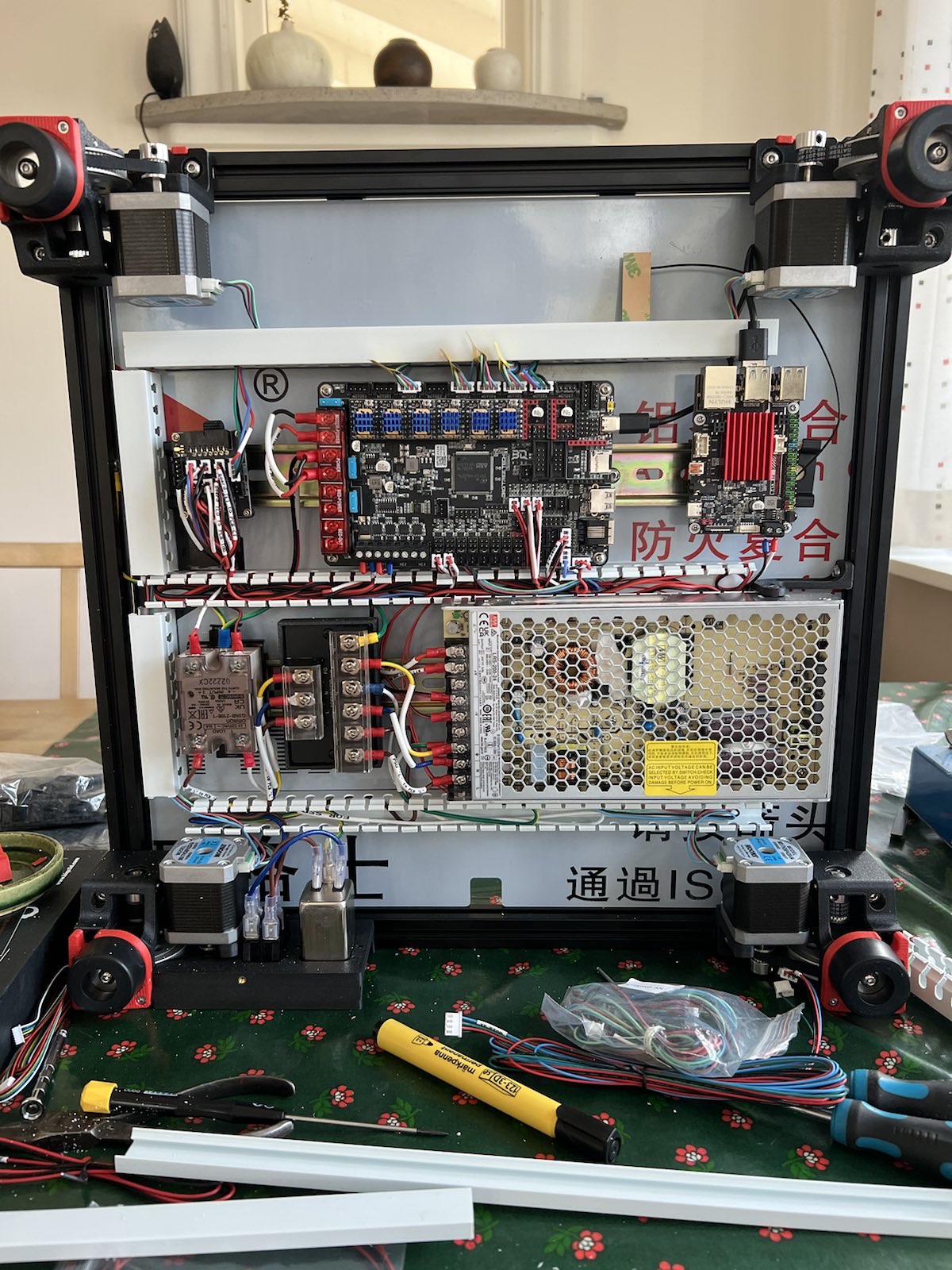
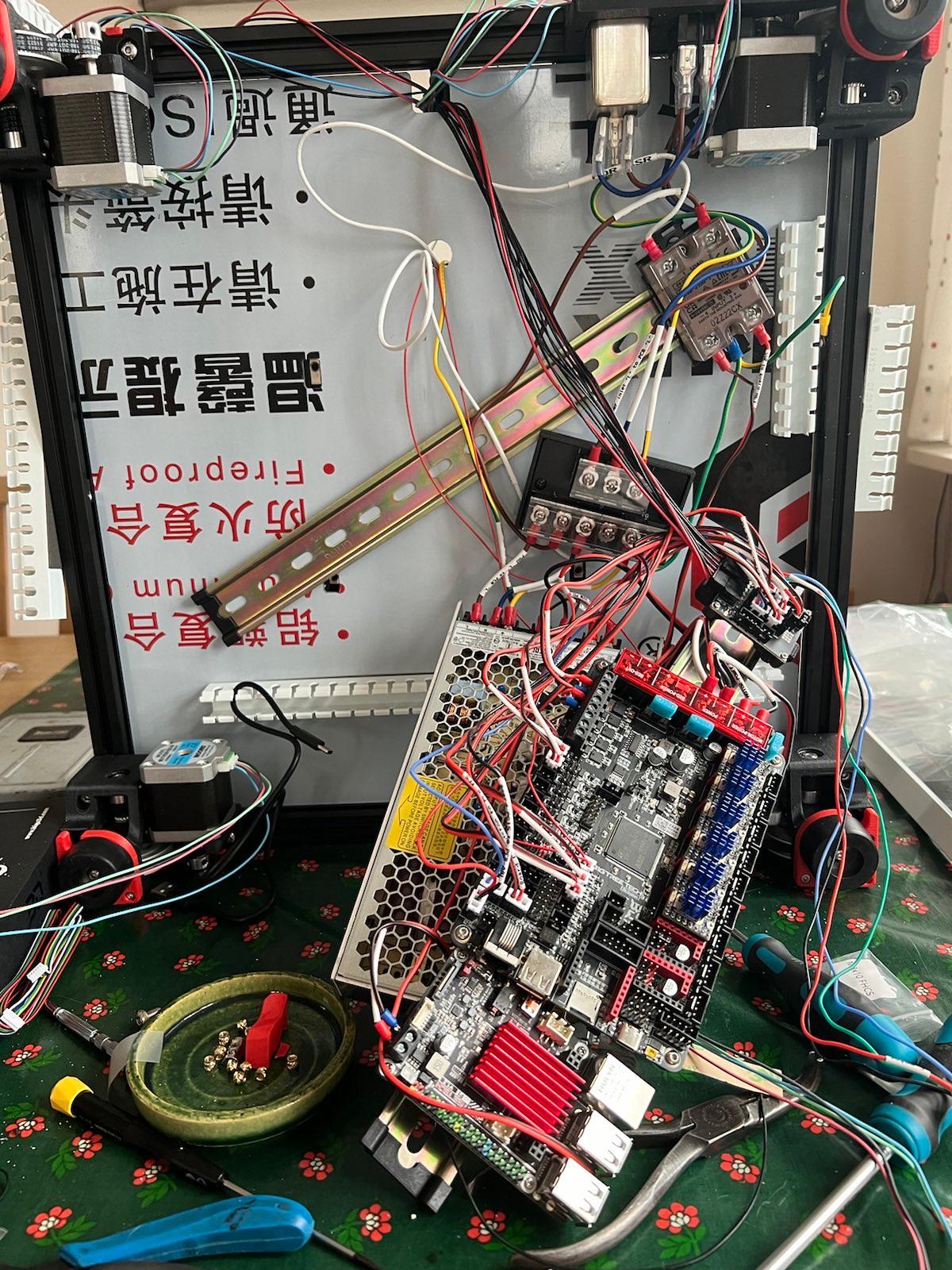
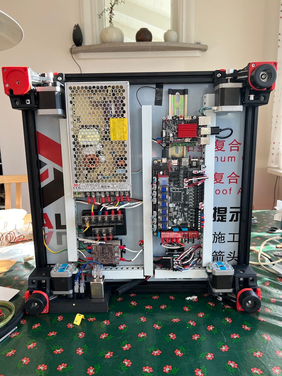
-
-
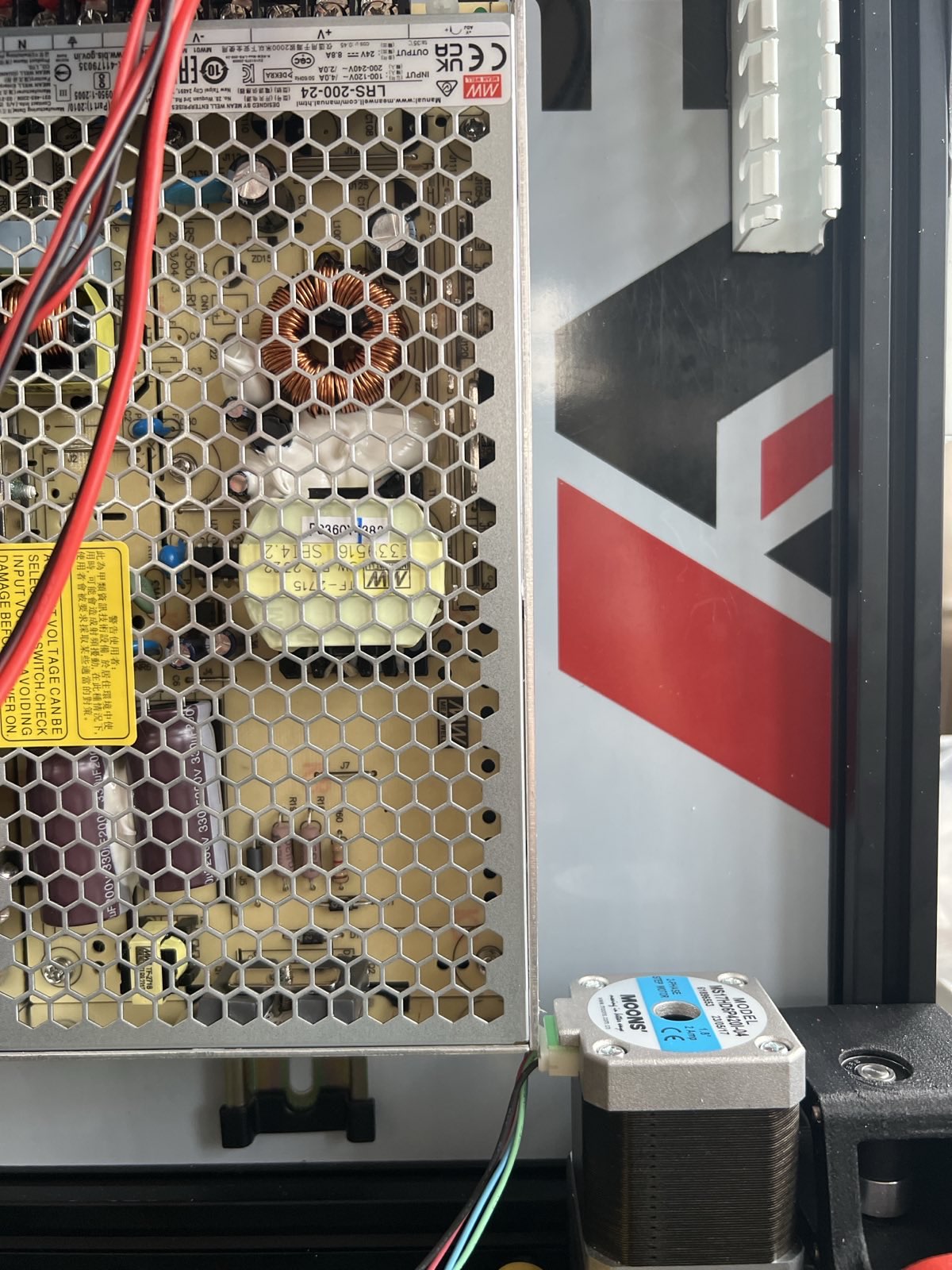
Here’s the problem with the motors on the 300x300 size. This i fixed by turning the motor 90 degrees so that the cables are pointed upwards. If you look closly this is done in the image above.
-
No mention to also drag neopixel cable, this you will probably find out after you’ve mounted everything making you have to redo the cable chains. If you have an octopus V1.1 it should be routed to the led pins, there should be three, this cable should be connected to the two on the USB-port side, with the 5V being closest to that side. They share ground with the rest of the board so that cable isn’t needed.
Minor issues
-
In the kit the M3x10 BHCS screws are missing. I replaced these with the M3x12 BHCS. I was a bit affraid I might regrett this when they are needed later but so far I’m not sure where they are used. The Formbot-kit also seems to include a few extra of every screw which is very nice.
-
On page 28 of the Stealthburner PDF, it’s not clear which way the motor is supposed to be mounted, I did mine the same way the video linked on that page showed.
-
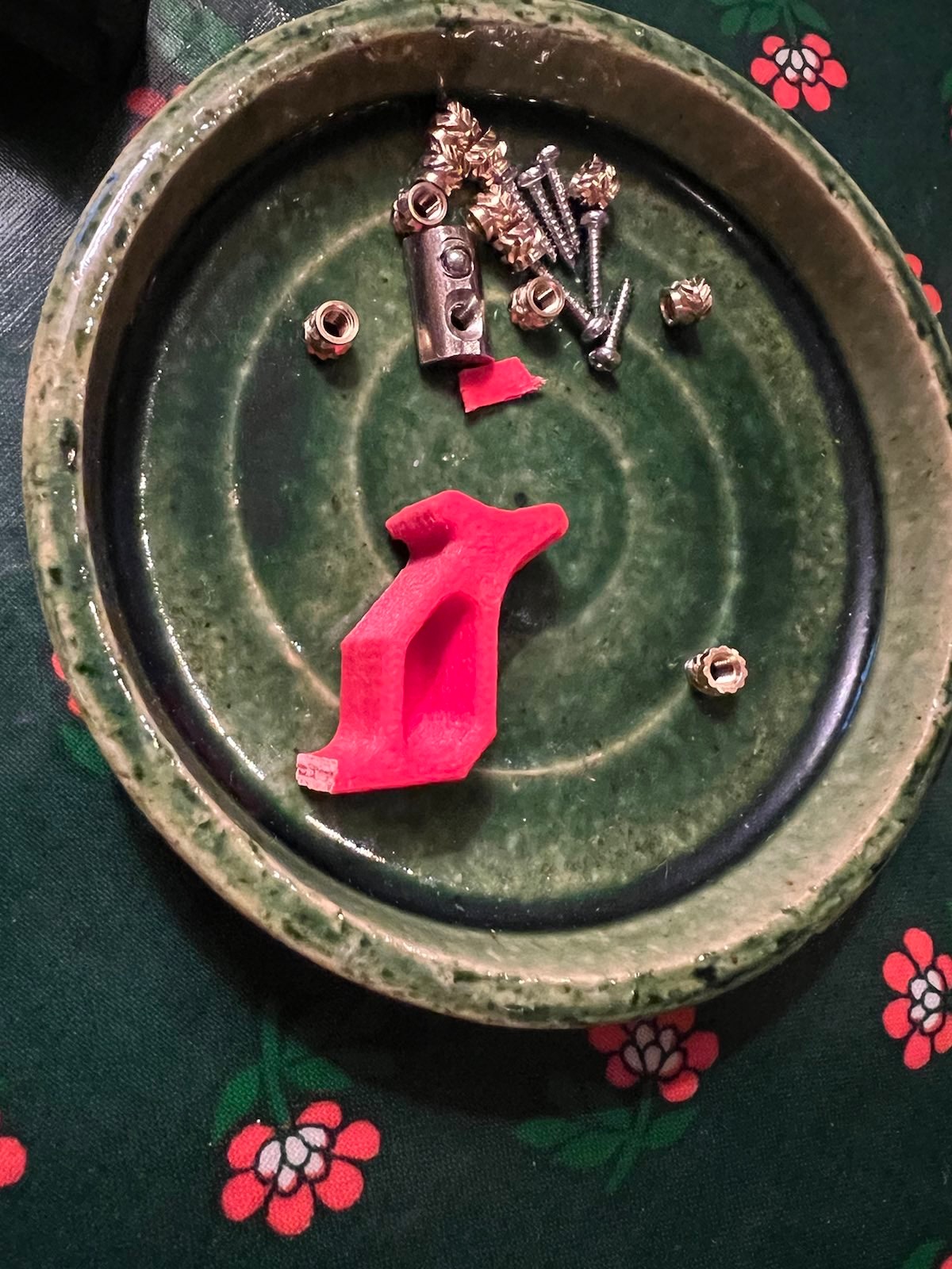
The original CW2 latch broke, this is a known issue. I hope the Voron team redesigns this. If you have access to a printer, or a friend with a printer ask them to print a reinforced replacement (i printed this one) before you even start. This could be PLA for now, it’s good enough. Just make sure to print a new one in ABS later.
-
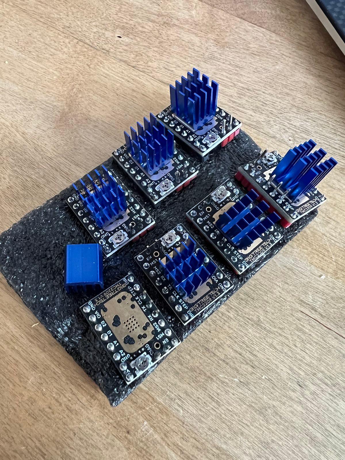
One of the stepper-driver’s heatsink was missing it’s sticky thermal pad. This is a BTT QA issue and has nothing to do with Formbot. I solved this with some tape and thermal paste for now. I’ve ordered the correct tape to change it with whenever that arrives.
-
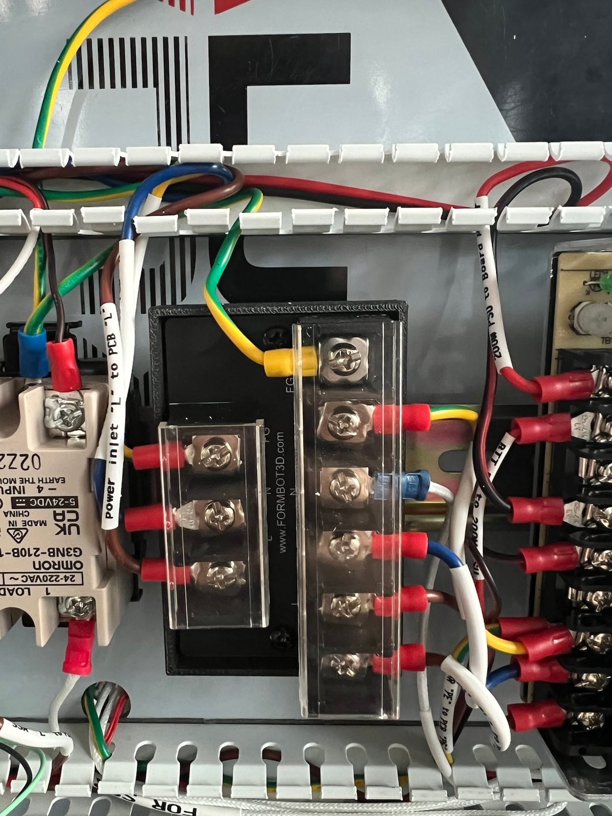
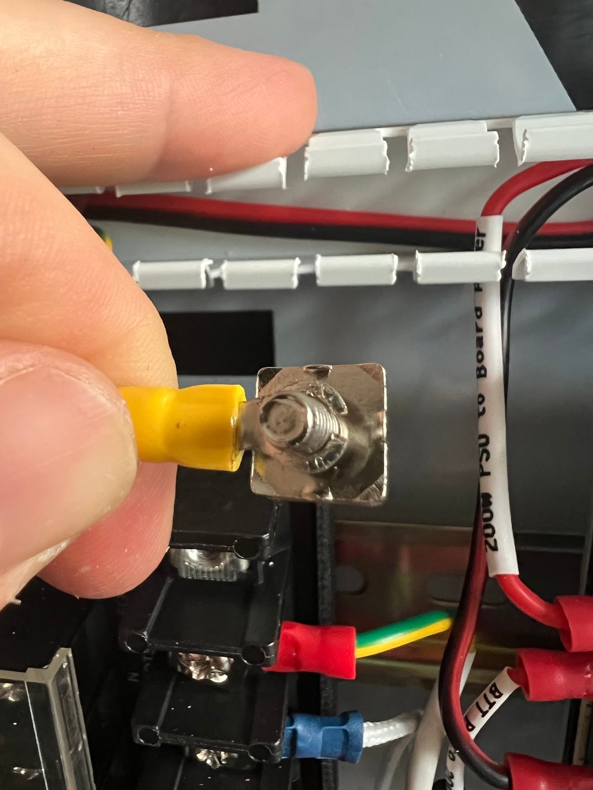
The split ground cable is a bit to short to make the routing nice, it also is to small to fit the screw so to make it fit one has to cut it.
-
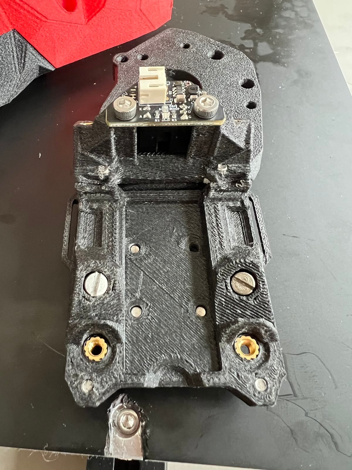
All screws in the kit are stainless steal, it’s nice for everything but on page 27 of the TAP manual. The two M3x6 FHCS needs to be magnetic. I had to find my own and change these out. Later in feedback I learned that this is the R8 version of TAP and that it works with four magnets as well, this might have been the solution Formbot intended. I will probably change these next time I remove the extruder.
-
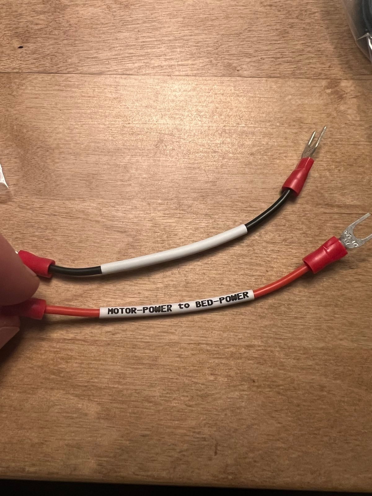
The cable below is wrongly labled. It should say “Power to BED-Power”. In later kits they’ve solved this with a sharpie.
-
The cable chains are kind of bad quality. A few of my clips broke. As I plan to do a CAN-bus mod I don’t care but if you’re planning to keep them I would probably change these out.
Notes
For anyone new here’s a breakdown of what is what.
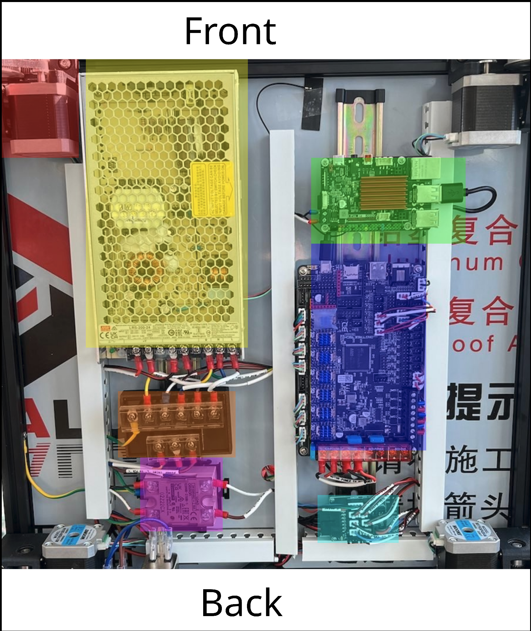
RED - Motor turned 90 degrees (Formbot 300X300 kit)
PINK - This is the on off switch for the heated bed, it’s not an invertor as one might think. In the Voron documentation this is called the AC BED CONTROL. To be specific this is a Solid State Relay (SSR).
YELLOW - PSU, the powersupply. In the Voron documentation this is called the LRS-200-24 PSU.
GREEN - RASPBERRY PI.
DARK BLUE - Controller. This board controlles the motors and is basically a break out board. Before Klipper this board used to run on Marlin and there was no PI. It’s a bit confusing. Just know this is refered to as the CONTROLLER BOARD in the Voron documentation.
LIGHT BLUE - Break out board (this is replaced with canbus is later kits)
ORANGE - This is Formbots own PCB, in the Voron documentation this is the same as using the WAGO clamps.
-
The plastic bracket included in the kit which is for a SBB EBB board isn’t needed. Just skip this.

-
To mount the SBB EBB break out board i used M3x6 screws from the kit.
-
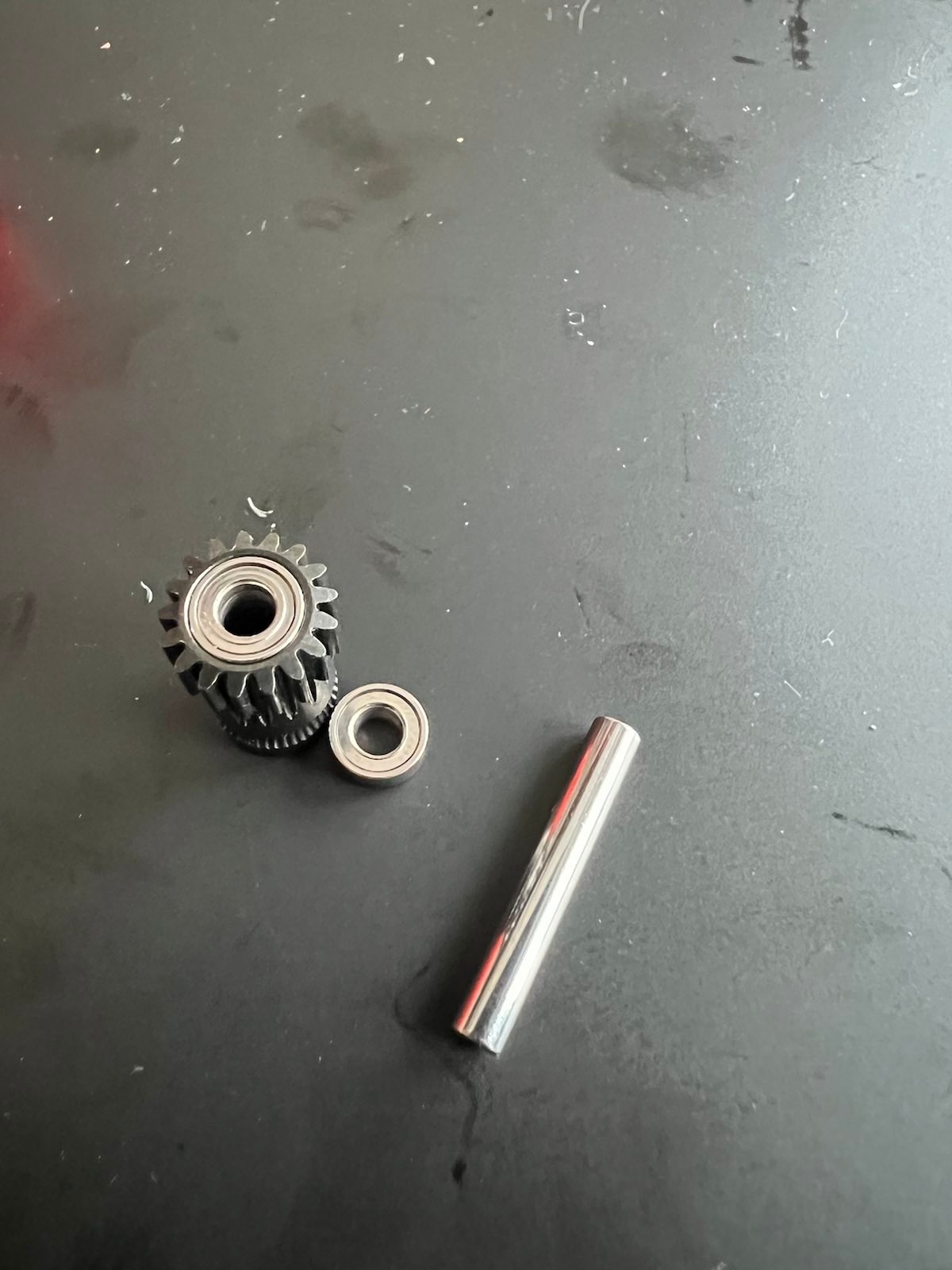
The Bearings on page 17 of the Stealthburner PDF are different from the ones in the kit. Not a problem, just be aware.
-
There’s no z endstop included because of TAP, there’s also no 5V PSU included because the BTT PI runs on 24V. Not a problem, just be aware so you don’t spend time searching for items that simply aren’t there.
-
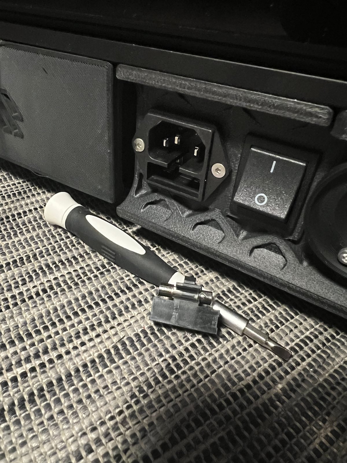
Don’t forget to change the fuse. It might be hard to know where to find it. Here’s an image. 4A for 230V and 8A for 110V. Here’s the nice explaination I got “The Bed has 650 Watt + PSU 200 Watt… 850 Watt / 230V = 3,7 Amp”.
-
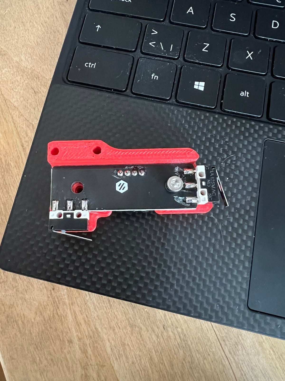
On page 163 one of the Voron 2.4R2 PDF the limit switches are installed a different way then the once in the kit, this does not make a difference, it’s just a bit confusing.

-
I found it to be unclear how many of what panel mounts are needed. But the STLs actually says that I noticed later. For instance bottom_panel_clip_x4.stl, the x4 is the amout needed. I printed these in PLA for now. I need the panels to print ABS so it’s a bit of a catch 22.
-
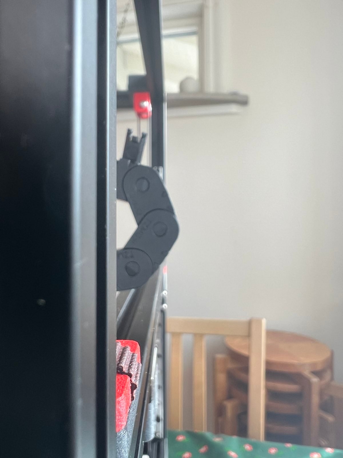
The cable chains are a bit too long, you can remove links so this really isn’t an issue. Rather nice having a few extra. A tip is to mount the ends separatly and connect them once all the cables are inside (as the snaps closing the chain will face down towards the 20x20 extrusion).
-
B-motor cable route, used instead of zipties
-
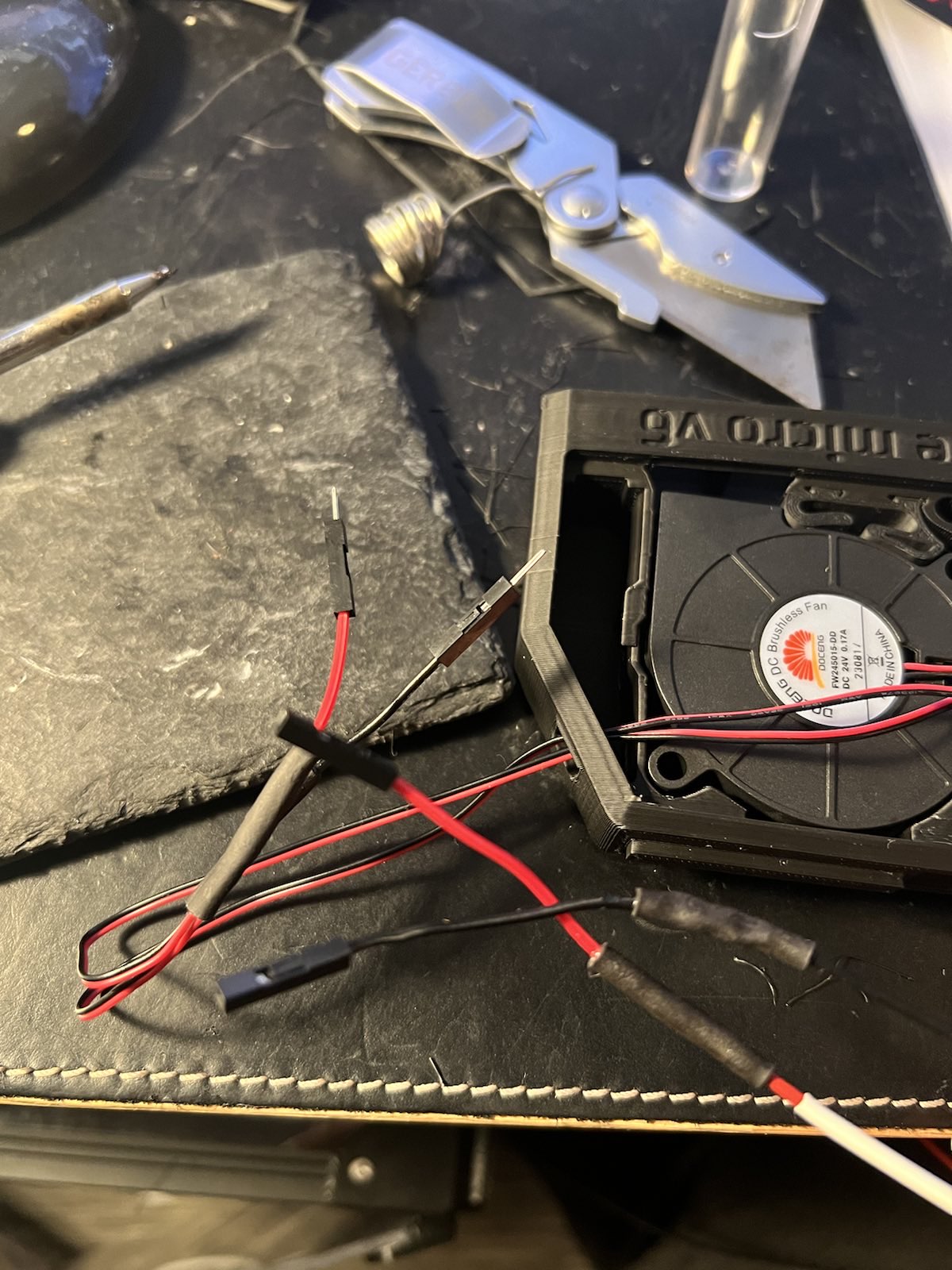
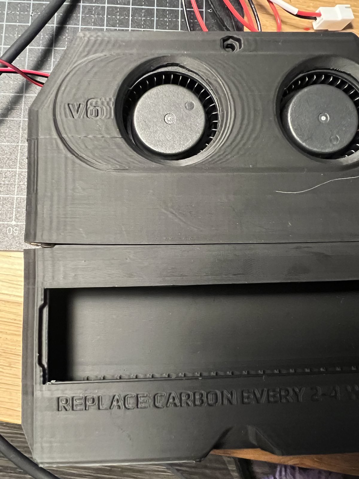
From what I remember, the kit said to include a nevermore filter. It dosen’t. It does include some hardware, fans, coal, WAGO-clips, a cable, some screws. But it does not include the plastic parts. This is a bit of an issue. I would want the filter to print ABS, but to do so I need to print the filter, in ABS. I opted to first print all panel clips in PLA and then print the nevermore parts with a window open. The printer isn’t tuned properly but I also don’t want to do that without the filter. So this is good enough for now. When the printer is tuned I will reprint this.
-
I can also say mounting this was hell, getting the heated bed back in place took some time. As you can see I choose to print the V6 version and not the Formbot version (if link is broken, they can be found here). I didn’t have a JST connector over so I’ve temporarily used other connectors.
-
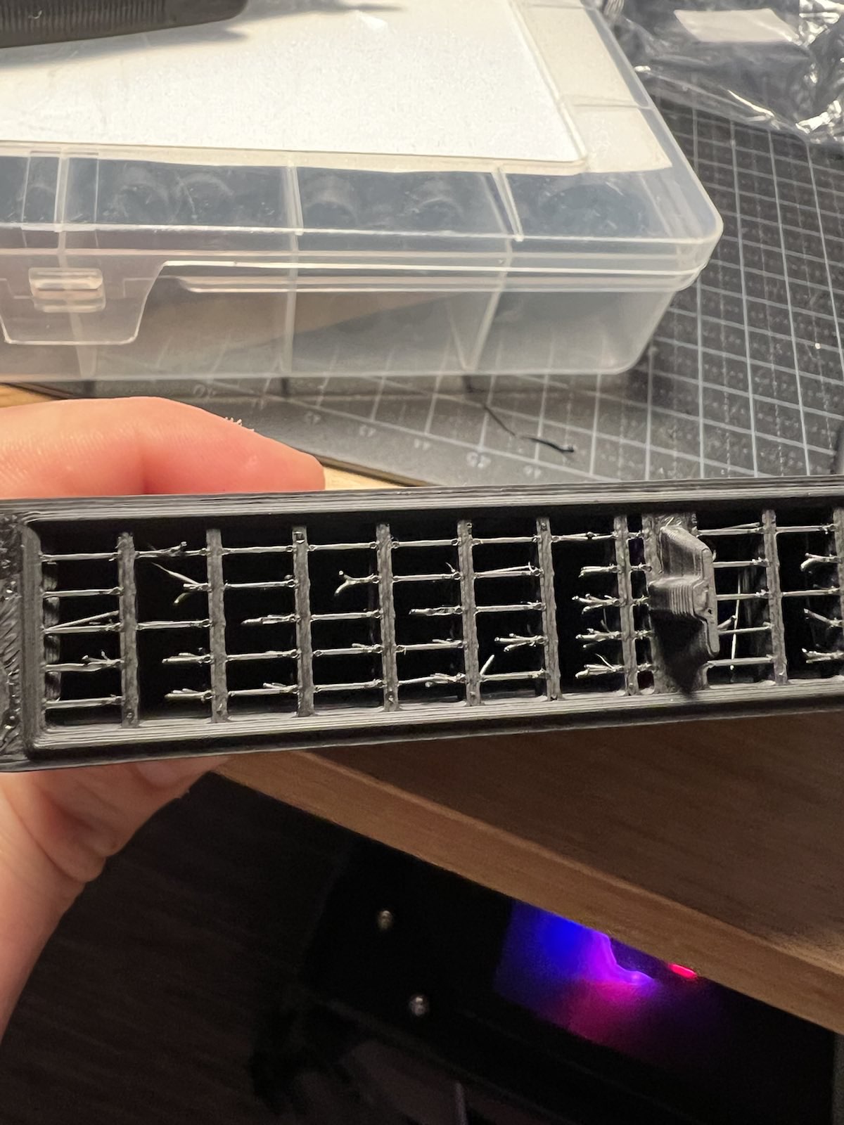
As you can see the non tuned printer has a bit of work ahead before it prints well.
-
As there were more 1mm foam-tape included I also added it to the inside of the doors which made a real impact.
-
When installing the Fly-ADXL345-USB (Mellow Fly used for imput shaping) I had some issues, first with getting the board into BOOTSEL mode and late when flashing. The first issue I have no idea of how it happened. I did the same thing about 50 times and all of a sudden it worked. The second issue was a typo from my side, please don’t forget
/dev/serial/by-id/in this command
make KCONFIG_CONFIG=config.adxl345 flash FLASH_DEVICE=/dev/serial/by-id/usb-katapult_rp2040_E662549553812C2B-if00
Summary
All in all it’s been a fun build. It now prints parts and seems happy. It took some time getting the config correct with all pins. I also mounted some led strips at the top of the chamber. I was a bit affraid of crashing the whole printer badly but thanks to the well written initial setup guide everything work out fine. Just remember TAP will figure out where true Z is. Make sure to put you z_offset to what it should be. I used TBD and that seems to work okay. Also remember there is a huge community, I asked for help several times when I needed it. Just be mindful it’s a community and not a support. I’m really happy I toke this project on and built what seems like a printer that will be my new working horse. Looking forward on tweeking it and improving print quality, one commit at a time.
If you’re interested in my config files they are available here.